1:48 P-39Q Airacobra

Arma Hobby's 1:48 scale range was recently expanded with P-39 Airacobra kits. “Q” was the first version to hit the stores and will be addressed here. Let’s check it out.
Disclaimer
The review sample was kindly provided by the manufacturer. Thanks, Arma Hobby.
Overview
Box with the catalogue number 40010 tempts us with quite neat illustration by Piotr Forkasiewicz.
Inside, an additional cardboard insert keeps the contents safe.
Which consists of a set of plastic sprues (three grey plus one transparent), self-adhesive masks, a decal sheet, instruction, metal weights and an errata (with attached 3D resin print).
All those pieces are completely new, so let's quickly move on to a closer inspection of the kit's components.
Plastic
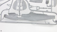
Starting with the fuselage, split lengthways into two main parts, just as it was done in the smaller 1:72 scale model, released earlier by the same manufacturer.
Its surface is covered with a grid of recessed, relatively fine panel lines. Some access panels clips marked, no full riveting though.
Because Arma Hobby opted for a “universal” sprue, accommodating several versions of the P-39, some details will have to be removed.
This also includes the position lights on the sides of the fuselage (just behind the cabin door, below the small air intake – for some reason marked with a raised line), which are completely overlooked in the instruction (not indicated for removal, yet absent from all assembly drawings).
The top carburettor air intake lacks the characteristic crossbar. Instead, we have small overflows of the plastic on the edge of the hole, and minor sinkholes at the base.
There are also other casting flaws in a few places, which may be caused by defects on the surface of the mould. These are small and easy to remove, but the impression is spoilt nonetheless.
The small air intakes at the front of the fuselage, which shouldn’t be intakes at all (on the contrary), will also require some attention. This error (which, incidentally, was avoided in the 1:72 scale kit) is addressed by the included errata with a tiny 3D print.
The cut-out visible just above them is for the fuselage gun outlets. Three variants available, but this time we will be interested only in the middle one (let’s leave complaining about the blurry barrels for the P-400 release).
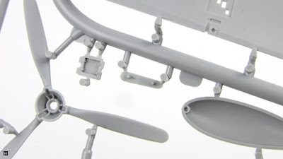
Another sign of the kit's multi-variant nature is the three-bladed propeller, or rather propellers – cause there are three in total. Building either of the machines featured in this set, you will use the one representing Aeroproducts' 11 feet and 7 inches prop (part 74).
Meanwhile, 10 feet 5 inches Curtiss (65) and Aeroproducts (73) ones will be left hanging on the frames.
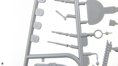
The spinner (53) should be fitted with 37mm gun barrel with shielding (19).
Among the parts you will also find a variant without the shroud (36) and a 20mm barrel (34) dedicated to the P-400, which will come in handy at another time. Drilling the tips will be a good idea for all of them.
Also coming from the P-400 are the twelve-pipe exhausts (8), which will remain on the sprue after one use the appropriate for this version six-pipe units (22). Again, no exit holes, so look for some “aftermarkets” if you don’t like to make them yourself.
Rear of the fuselage is where the stabilisers belong. The vertical (51+52) and horizontal one (56+57), both made from two pieces.
The corresponding control surfaces were designed as separate components and can be tilted without any fuss. Both the rudder.
As well as the one-piece elevator – this time with the right number of trim tabs (in contrast to 1:72), but also with some small imperfections of the casting.
The ailerons and flaps are a different story.
The issue of riveting the wings was left mostly to the modeller.
Reflector recess can be found under the left wing. The rest of the airframe lighting was reproduced directly from the grey plastic (which could already be noticed on the vertical stabiliser).
Radiator air outlets, located on the wing underside, are covered by inconspicuous flaps (9, 15, 31).
The leading edge air intakes are divided between the lower and upper wing parts.
These are completed by the element (40) which is also the rear wall of the front wheel recess.
Wing machine guns (24, 25) won't be used this time, and the corresponding shell ejection holes should be sealed (something the manual forgot to mention).
Note the differently shaped mounting slots (in the wing upper halves), helping with the barrels arrengement.
Elements of the main landing gear bay have been reproduced on the inner surface of both the upper and lower part of the wings.
Small covers (54, 44), made together with the part of the bay sides, comes with struts (28, 29).
The outer ones initially caused AH some problems, but more on that later.
The main wheels evoke some mixed feelings. For we have absolutely bald tyres with tiny markings on the sides, and a small flaws of plastic on each half (on the tyre, right next to the rim).
For the front, there are two versions available.
Assembly of the front gear (99, 48, 33, 13) involves bending one of the components (13), which of course is mentioned in the instruction.
The front bay covers, designed as separate elements, feature some details on the inside.
Meanwhile the bay itself sports raised rivets on the structural elements.
Enclosed from the top by a shelf with an outline of the cannon and machine guns ammunition boxes. Plus indentations for the metal weights on the other side.
Front wheel compartment ceiling details can be found on the part that is also the floor of the cockpit, which was designed together with the propeller drive shaft cover visible in the landing gear bay.
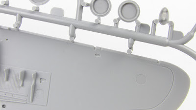
Since we mentioned the cockpit – let's take another look at the fuselage halves, this time from the inside. The half-circle recesses are for positioning the cabin elements.
The designer has stuffed here quite a lot of equipment details, such as a number of control instruments, which look quite OK.
Just like the instruments panel, which should be supplemented not only with a dials in the form of decals, but also a gun sight (11).
Front wall of the cockpit was reproduced together with the rears of the fuselage machine guns, which have to be bent back accordingly.
At the other end, behind a pretty decent pilot's seat, goes the frame with additional armour. This time, the glass panel mounted behind the pilot's head has not been forgotten – it is on a transparent sprue, of course.
Installing the radio (75+76) on the shelf located behind all of this, requires drilling the holes marked on the underside.
Now a word about loadout. Single pylon can be installed underneath the wing centre (by first drilling the appropriate mounting holes, marked on the inside).
On it, a choice – an extra fuel tank or something more deadly.
Additional gun nacelles (32, 33), characteristic of the P-39Q, need some barrels (34) trimming.
Finally, let's have a look at the Pitot tube (5), the dorsal antenna (26) and the radio direction finder antenna (4) with its base (80).
The last two parts will be left unused this time.
Absent errata
One more 3D print was included in the P-39Q kits initially offered by AH (in addition to the tiny outlets mentioned earlier) – the main landing gear covers.
For a simple reason. The designer of the model apparently forgot to mirror the part after copying it and we got two identical pieces on the sprues.
The presence of the printed covers in the box hints at another problem, some would say traditional for AH – sinkholes on the upper surface of the wings.
Both of the above flaws have been eliminated during the production and should not be encountered any more – unless one buys a second-hand kit.
Transparencies
Airacobra is in several respects a rather unconventional design for a single-engine fighter from the Second World War. It is, for example, one of the few machines of its kind with a “car type” doors. In the model those were designed as a separate parts, which makes it possible to install them in open position (although it is worth remembering that the left one was opened much less frequently).
The rest of the cabin glass was prepared as a single piece.
Three more details can be found on the transparent sprue – the aforementioned armoured glass panel, gun sight supplement, and the under-wing reflector glazing.
All of a pretty good clarity.
Masks
Included self-adhesive masks will simplify the painting of both the cab windows and the undercarriage wheels. The inner surfaces of the cockpit doors were also taken into account here.
For some reason, the drawing in the instruction doesn't quite match what we have on the sheet. Fortunately, additional markings can be found on the masks themselves, explaining the purpose of the less obvious elements.
Weights
Just like the smaller AH Airacobra kits, this box also comes with the metal beads which should be used to weigh down the nose of the model.
A suitably shaped space was prepared above the front undercarriage bay.
Decals
This time the well-know Cartograf company was responsible for printing the included markings sheet. Closer inspection of the piece reveals nothing to complain about.
The print is clear and the colours are saturated and uniform.
Two sets of crisp stencils (ones with the printed background are for the repainted sand-coloured machine).
The sheet also contains the wing walkways, markings for the propeller, instrument panel and the seatbelts.
The overall impression is, as usual, very good.
Manual
The booklet with step-by-step build guide is typical for AH. Clear and easy-to-follow assembly drawings sprinkled here and there with additional comments.
Suggested paints listed in a table.
The paint schemes, as usual in colour, with the main markings arrangement key.
Stencils layout is shown on a separate diagram.
Digital bonus
Included errata also contains a link for downloading a STL file with accessories for 3D printing: two seats with belts, machine gun locks, trim control knob and oil cooler shutter.
Of course, access to a 3D printer is essential in this case.
Painting options
The kit in question comes with markings for three machines, which are traditionally advertised on the back of the box.
P-39Q-1 Airacobra, 46th Fighter Squadron, 15th Fighter Group, Makin, Gilbert Islands, late 1943.
P-39Q-10 Airacobra, 363rd Fighter Squadron, 357th Fighter Group, pilot Lt. Clarence “Bud” Anderson, Oroville, California, October 1943.
P-39Q-15 Airacobra, 68th GIAP, 5th GIAD, winter 1944-45.
No bonus this time. Oh, well…
Summary
Looking at the sprues, it is hard to shake off the impression that this is, to some extent, a step backwards from the manufacturer's previous models. Arma Hobby set the bar really high with its 1:48 Hurricanes, which feature, among other things, some excellent surface details. Meanwhile, the Airacobra seems to have been designed with a slightly different approach and is in this respect considerably simpler, not to say lacking.
The change of the tooling workshop responsible for the production of the moulds and injection process, reported by AH, unfortunately affected the quality of the plastic parts. Some flaws, such as the widely commented sinkholes on the wings, were fortunately resolved during the production run. However, it is apparent that there is still some improvement to be made in this area.
Nevertheless, the new Airacobra seems to be a pretty solid option for modellers who don't mind the fighter's controversial beauty.


